Showing posts with label wiring. Show all posts

Wednesday 24 March 2021

Boot wiring

 Again before the final fit of the fuel tank wanted to secure the boot wiring ,this has to be done with clips no more than 300mm apart .we used p clips and self tapping screw to secure the wire .

The fuel pump wire was the starting point as that goes though a hole between the 2 fuel pipes, i used a 20mm plastic fitting to grip the wire ,my idea was to leave the fuel wires as long as possible so i could fit the fuel pump wires to the pump before fitting it back ( not a lot of room ) and be able to take it down if needed 

fuel pump wires threaded though 

initially i planed to route the cable round the outside edge of the boot but the self tapping screws would be seen , so opted for straight across and protected the wire with so 15mm foam .

amongst the wires are cables for heated screen and boot light which i don't intend to use so will tuck those in the gap at the side of the fuel tank ,apart from the obvious cables that feed the lights there was also a another connection which is the number plate light I plan to take that up the side of the car to the boot hinge ..


Friday 26 February 2021

Wiring Alterations

 There are some wiring loom alterations that are mentioned on the DVD but not obvious enough for me to have seen before fitting the wiring .

First change is to the horn relay .

The relay has a feed to it and requires an earth impossible to change while its fitted 

Horn relay is the 3rd from the back 

The purple loop need cutting and replacing with an earth .

loop can be seen 

loop replaced with an earth 

Second Change is the  fuel pump feed wire, the wiring is fed from an ignition live from the fuse box and on my car the fuel pump is fed from the ecu so the pump wire has to be cut from the fuse box an attached to the ecu fuel pump wire .

fuel pump wire cut from fuse box 

As this ignition wire is no longer required i intend to use this wire for the feed to the electric seats and the reverse lock out switch .

Third change is to the washer pump again the feed needs removing and replacing with an earth wire 

feed(green wire removed and replaced with an earth 

Monday 15 June 2020

Dashboard Part 6

After labeling the wires it still just seemed like a maze.
Set to and started at the hazard switch end.
Needed  the technical files section for the wiring diagram from the GD disc then hoped the rest would sort of  fall into place .
I have a key switch separate from the steering column and the  hazard switch were Andy at GD puts his so guessed  the wiring would reflect this.  
Key switch and hazard switch as a starting point 

Hazard switch wired and connectors for the stalks  

Next was to tackle the switches I noticed there was a cut out at the top and I didn't want to see that so mounted the switches upside down
The cut can just be seen 

I then had to sort out the wiring as the light switch and the heater switch are both 2 position but the side lights to stay on when headlights are selected .
sorted this out with my meter and came up with
connections for the switch upside down 
Will require a link wire between 1 and 2 
once the switches were done most of the wires dropped into place ,I had a couple of issues  first is the illumination of the start button I needed to be the oil pressure wire so had to lengthen  that ,
Some of the gauges didn't have the terminals marked up so used a 12volt source to check and at the same time checked all the lamps (and found the start button doesn't light up )
 and I had no wiring diagram for the speedo or tacho in the box . the tacho was straight forward once I looked on the web but the speedo is not so easy -email to Andy then .

Starting Again

Who would have thought that half way though March our world would turn upside down ?Still cant believe it ,
The whole car building process just got put on hold with all the other things going on but now can finally get  a bit of time back on the car .
Fitting the battery seemed to be an easy  next step
Didn't like the bracket idea as less holes in the bulkhead seemed to be the way forward to me  ,trip to the scrap yard and got a battery strap off a car that I think will work fine .
Battery cradle fitted with my strap secured to the back fastening  

Battery fitted  ready for cover plate to go on 

Wednesday 22 January 2020

Horn

I was always going to fit air horns like most other cobra builders but also wanted to be able to use the horn at times with people dying of shock .Guessing that there will be a delay before the air horn starts hit upon the idea of having a smaller horn as well so just a blip would only sound the little one . only time will tell if this works .

Stobel Air horn ready to be fitted

Little horn fitted under the header tank
Plan to put the Air horn relay on one of the 2 spare rivnuts  in the picture

Wednesday 31 July 2019

Wiring part 2

After the success of the speedo sensor did exactly the same thing with the reverse lock out sensor.
Lots of mixed feelings about this do I :-
1 :- Leave it as reverse can be still selected its just hard to push across.
2:- Do a mod to weaken the spring and then leave it.
3:- wire it in on a switch to be somewhere on the dash .
Didn't fancy option 2 as once modified  it's do or die and knowing me it would have been die !so went for option 3 and  wire it and then I can decide later .
Once wired it was a simple case to feed the wires to the right hand side and loom everything together on the right hand side and I used the brake pipe to tie wrap the cables to reverse lock out the speed sensor and the reverse light switch all together
reverse lock out switch loomed up

speedo sensor with the reverse switch wires from the other side

wiring continuing and picking up the reverse switch
Used self amalgamating tape as think it looks neater than adhesive tape.
Moving on to the left hand side it was a mirror image of the right until I got to the end of the engine .
extra cables were the air intake sensor ( which goes in the intake tube) alternator wires and the cam position sensor.
wires at the front of the engine
 Again used SAT and "P" clips in any hole that would do ,the right hand side cables are the alternator ,the left cable is for the air intake and the middle one goes down to the cam sensor .

Mine didn't fit and looked like a completely different plug , After a beer and a think realised that the cam sensor has a link extender wire on it ,once I removed that the cable fitted no problem .
Cam sensor with the extender cable still in place

Wiring done good day in the garage .

Wiring part 1

Been putting off the wiring loom but can't any more. Getting it out of the box was the first milestone and then I needed a beer! .
Using other peoples blogs and pictures that I took when at the factory I sorted out the staring point was were the loom splits to feed the two banks
loom laid in the right position  loom is marked nearside and off side


 Then I started laying the 2 sides and hoped that things would fall naturally into place which most things do.

off side loom with the injectors and coil pack falling just right
The loom splits up just before the first cylinder and goes down the off  side of the engine  for the O2 sensor knock sensor the starter motor cables and the all important crank position sensor. The only way I could gat the CPS fitted was to take the starter motor down again.

Crank position and the knock sensor ( with starter removed ) the bottom one is the unused oil level
I noticed a wire that said coolant temp with nowhere for it to go eventually  I found a blank on the right hand side with a temp sensor in the box of tricks , hey presto the supplied sensor fits in there with the  doughty washer
coolant temp sensor (for the gauge not the engine ECU which is the other side
Following on from this was the starter cable  together are the alternator supply cables  and the other cable is the start request signal really tight for space to clear the exhaust.
showing the alt cables and start cable ( used "P" clips in any vacant hole to try and tidy up the loom

moving back to the top to finish off was the last 2 sensors which nicly fall into place on the throttle  body and map sensor
 
off side done
Last job on this side was to fit the off side O2 sensor which connects up but way too much cable so coiled it up to keep it away from everything and tie wrapped it to the frame.
O2 fitted and all the cable tie wrapped out of harms way

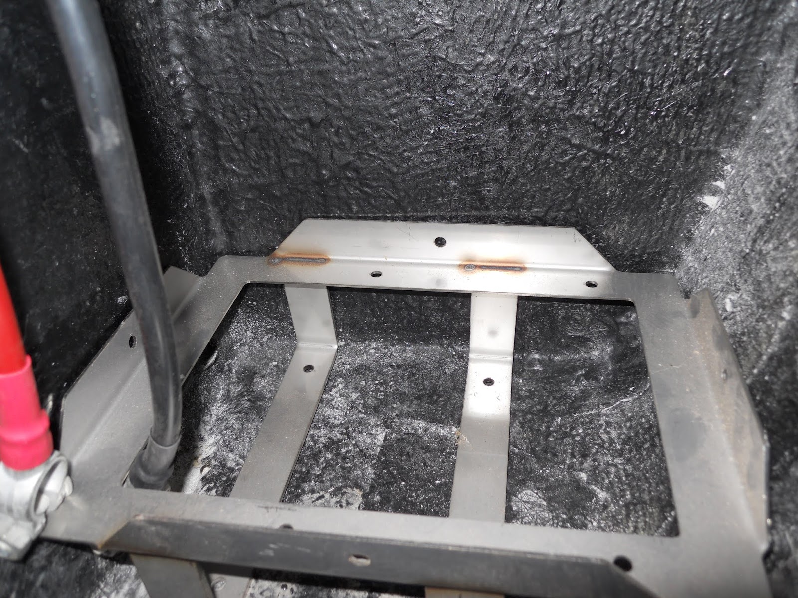
Before moving to the near side I had the speedo sensor to think about ,The plug is special order from the US with an extra 30 dollars to get it here yer right, so a bit of thinking later and !!
speed sensor

took out the speedo sensor and cut the shroud off to expose the pins


and then crimped 2 red though connectors on to it
crimped happy days
 
then is was just a matter on putting the shroud back on and filling it with epoxy proper job

Tuesday 21 May 2019

wiring

Now I have the seat wiring I can complete the loom
Wiring is colour coded for right and left which helps .I also decided to put an extra pair of wires in at the same time just in case .
Drivers side heater cable +2 spares
 Looking at other blogs and the IVA needs clipping at at least 300mm so I copied other blogers and went for 250mm
left hand side has carried the main loom as well
used 6mm clips on the drivers side and 10mm clips on the passenger with stainless self tappers and washers .


Wednesday 3 April 2019

Light wiring

Next task was to start with the wiring started at the drivers side and worked my way round .
Using the GD diagram the wires.  are quite straightforward .
Knowing how much water plays havoc with wiring wanted to make sure in the unlikely event of being caught out in the wet at least the wiring would stay dry .
Placed heat shrink on the headlight  cable so that no water could get in the cables and used the bullet connectors supplied to connect up followed by adhesive tape to seal it all in .
At this point I was not happy with how exposed the indicators were so decided to try and protect them a bit .
After some thought cam up with half a tennis ball  ! I extended the light securing screws with 5mm barrel nuts (tool station ) and then fastened the tennis ball with 2 more 5mm nuts after painting think it look better only time will tell .
Still wet should blend it when dry !

As in the same picture fitted the mesh covers at the same time these were fabricated  by Steve whilst laughing at my tennis ball idea ,he  had to make a wooden template to form the mesh round as the hols were already cut so couldn't use the piece cut out and have to say fitted first time .

Wednesday 6 February 2019

Battery cables

Had a bit a time today so fitted the battery cables I copied Dales post and fitted the Positive at the bottom ,although my set differed from his as only had rubber protectors on the engine side ( will need to clarify that with Andy )
Also the main wiring loom supply that I fed in above the heater what seems like an age ago needed to be fitted to the positive as well which needed filling out to fit !
another little job off the list. also fitted the heater plug at the same time ,The heater is three speed and the wiring is for 2 speed using the diagram on the side of the heater went for lowest and highest ( can always change my mind )
Batt cables from the inside showing the main loom feed and the now wired heater plug

Also dropped in the battery box to test for fit ready to bolt though the floor on next visit .
seems to be too many holes just for a bat box more reading required  


Tuesday 1 May 2018

Courtesy lights

 On the wiring loom there is the facility to have Courtesy lights operated by door switches so figured if its there why not .
Bought the door switches from Amazon via China at two quid the pair.
Holes drilled

Then fixed with 4mm countersunk nut and bolt my first idea was self tapping screw but the switch will need earthing to work and the bolt will provide a better and easier earth
Fitted with bolt (free advert for Aldi Butter ( keep bits and bobs in them )


Front wiring loom

Took the front loom out of the box and tried to make sense of it ,wiring loom in one hand and the GD manual in the other and all the wire in front of the engine grommet made sense ( worry about the back bits another day .
First job is to fit the fuse box and it matters which way up it goes ( fuse 1 needs to be at the top !)
again the hole was already cut out for me except it was bigger than the fuse holder in places secures with the bolts and black Silastic
Fuse box fitted the Silastic can just be seen

Secured the wiring loom with 10mm "P" clips to the bulkhead

Part of the loom goes thoughh the left inner wing (used a 25mm grommet) and then doubles back on itself for the indicator repeater so used the same bolts ( less holes!)
Wiring loom doubling back

The rest of the loom then goes across the bonnet stay to supply the drivers side lights secured with 2 5mm rivnuts
View from the nose cone the slack is to accommodate the engine air intake
and the wire hanging down is the feed to the rad fan  


The wiring loom then mirrors the left hand side to supply the drivers indicator repeater .


Boot light

Attempted to find the hidden wire in the boot today as the number plate light wiring is put in before the boot is made and just coiled up  read other blogs and didn't think this would be very easy but found it first go well pleased


Wire found and pulled though
 
 However fitting the unit wasn't quite so straight forward as it comes with studs already on and the boot is double skin so studs are a no no

Light unit with studs


Solution was to drill the studs out and fit 4mm rivnuts to the door sorted. 

Tuesday 27 March 2018

Rear wiring loom

After reading the GD manual it recommends doing the rear loom first Andy was kind enough to point out to drill the hole at the bottom near side of the boot .I did this and then opened the hole out to accommodate all the wires .
The loom has to be fed from the cockpit . I was lucky as I could spring the top part of the mould with a wooden wedge to allow the cables to go in without having to drill a second hole
Hole from the boot


Cable coming down from the cockpit