Friday 24 May 2019

Engine work (Gear box)


Attaching gearbox to engine

 
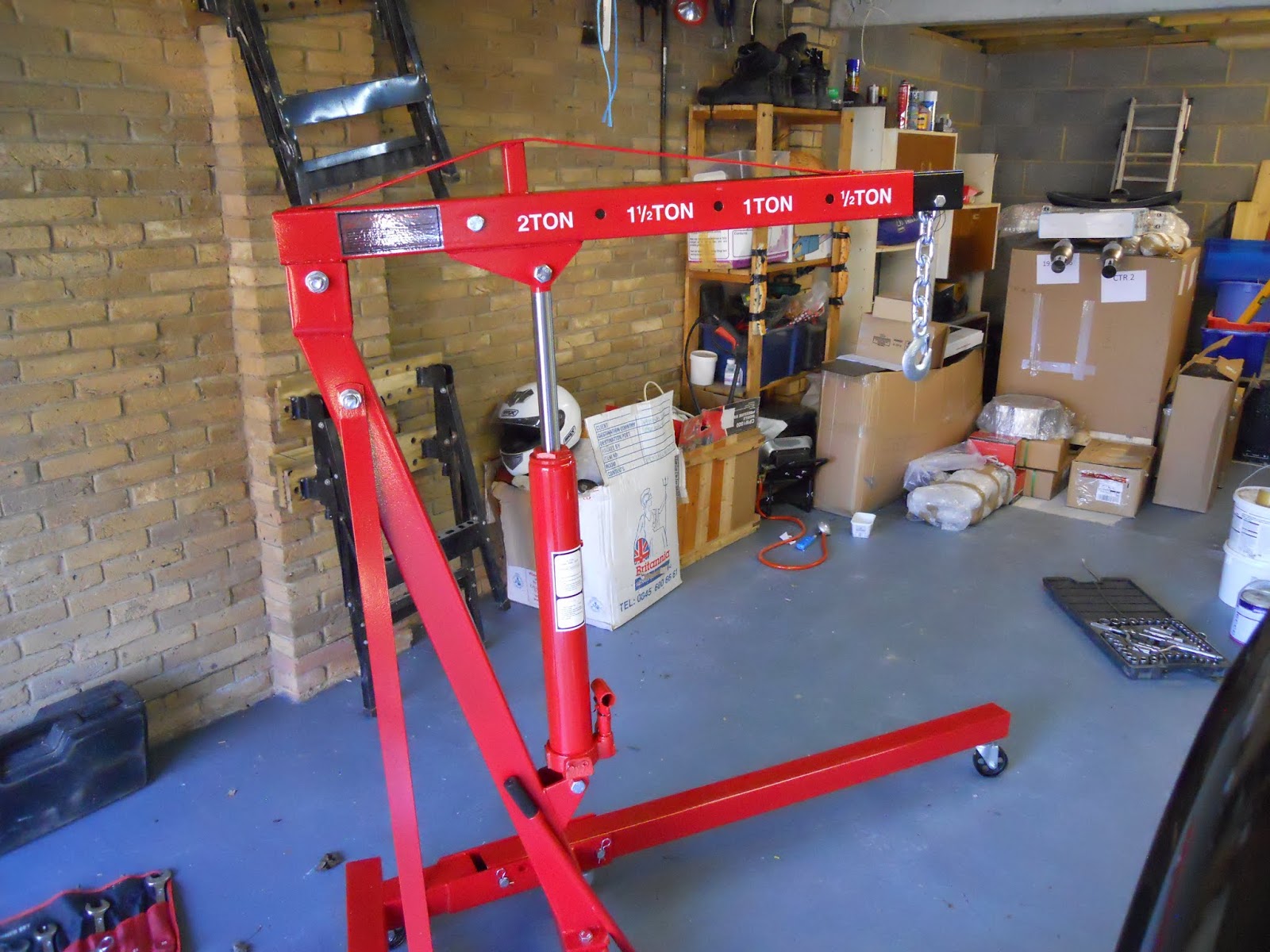
The end of the gearbox output shaft was lubricated with lithium  grease and  using the engine hoist and a couple of slings, the gearbox and bell housing were offered up to the engine.


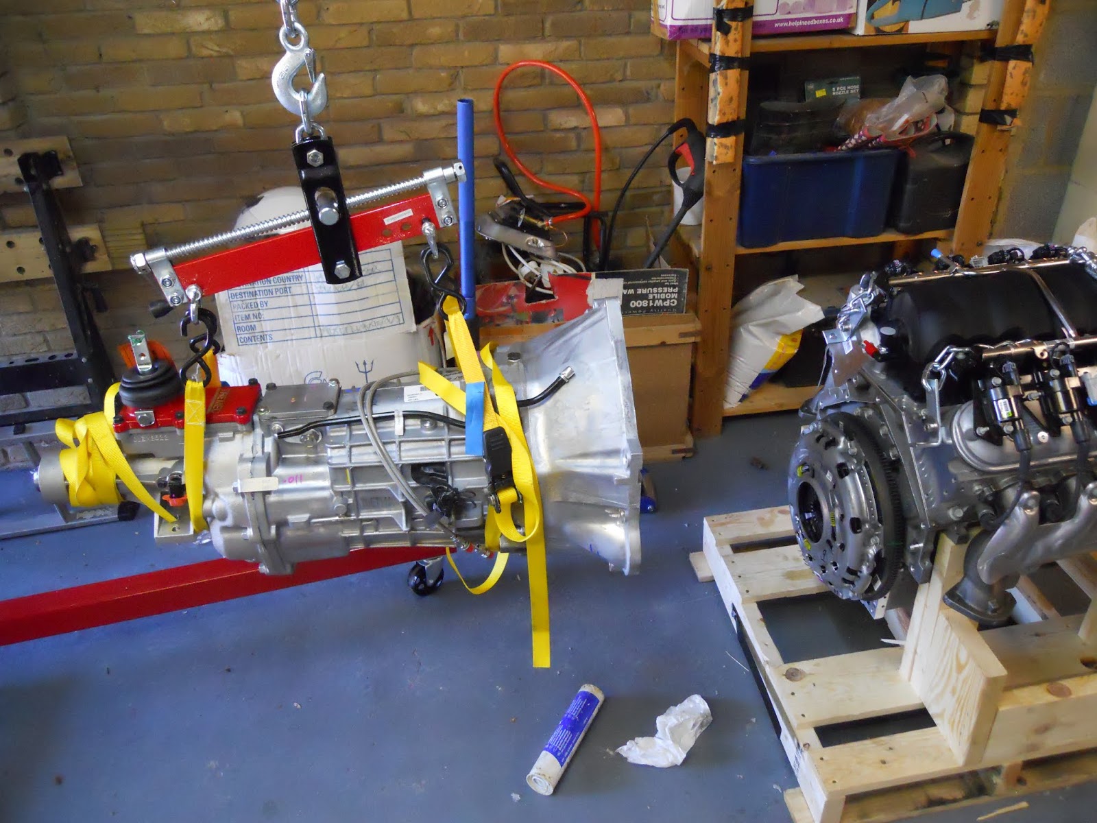
 Making sure that the shaft was lined up, the bell housing was then twisted a little and pushed home over the locating pegs. The bell housing was then bolted up to the engine block using high tensile bolts and torqued to 40  ft lb. Thread lock was applied to these bolts before tightening.

Fitting the unit in to the chassis

 The radiator support frame and the two removable cross member from the front of the chassis were removed (the top brace and the diagonal).


The engine mounting adaptor plates were  fitted to the engine and only go on one way ,  Each mount has to have the bump ground off and then I painted these with stove enamel .
 
The gearbox selector was removed and the hole covered up with masking tape
 
 
 Using the hoist and the load leveller which is a great piece of kit  we manoeuvred the assembly in to place. Never took any pictures here as was too busy  with the 10k Engine and the 10K chassis .
However it all went fairly straight forward  just needs to be tipped in first then leavaled out (load leavaler came in to its own here great tip from Andy ) forgot to remove the brake pipe braket and the engine doesn't go past this so quick break while everything is in the air to move this
 
Got the engine sat on the gearbox mounts then realised that I hadn't fitted the propshaft so had to take it out a bit. The prop shaft was inserted in to the tail of the gearbox, lubricating the gearbox seal with the gearbox oil.


 The engine mounts were then slid in to place, over the chassis mounting points. The long bolt and nut were used to secure the mount to the chassis. The three supplied hex set screws were then inserted through the mounting in to each adaptor plate.
Engine in I can relax now
 
Couldn't get the gearbox rubber mount to fit into the gearbox even after removing the rubber in the threads .
M12 bolts seem to be supplied but the thread looked M10 .
Just left it in place and look at this another day .
Good days work and enjoyed it ! Huge thanks to Steve again
 
Cross braces back in place Note the wheel sliders which are so useful
 

Engine work (gearbox)


Fitting the release bearing
 
The clutch release mechanism is a modified (by GD) hydraulic bearing, with braided hoses fitted.
Mine as other blogs didn't fit so I had to open the bottom slot a bit with a de burring tool . Remembering to protect the gearbox bearing from flying aluminium .
 

Slot opened  in the gearbox

 
Now it fits
 
The hydraulic release bearing was located over the gearbox output shaft, with the outlets aligned with the slots in the gearbox. The release bearing was bolted in place with the two M6 set screws supplied. Both screws had thread lock  applied. The bottom  hose is the bleed pipe.

 Fitting the bell housing

The bell housing was attached to the gearbox, using seven new high tensile bolts. These bolts were thread locked too.
bell housing attached and torqued up ready to fit to the engine


Engine work (flywheel and clutch )

First job was to change the original sump for the supplied shallow one .
Quite simple job after first removing the original flywheel
Flywheel removed
Then the sump and pick up is changed straightforward job very low toque setting on these bolts only 8 ft lb


New sump fitted
 Flywheel fitting

,I fitted the spigot bearing in the end of the crank shaft only goes in one way with the bevel facing outwards
Spigot bearing fitted to centre of crank
 Fitted the flywheel after checking both faces were clean and e used the bolts that I had just taken off


 The bolts holes on the flywheel were marked 1 to 6.
The build manual doesn't seem to cover any engine work so got the toque setting from the LS website .(https://paceperformance.com/files/pdf/ls3-torque-specs.pdf)
The bolts were tightened in the following sequence 1, 4, 2, 5, 3, 6. Thread lock was applied to the bolts before they were torqued. They were tightened in three passes as follows:
  • 1st tighten to 15 ft lb torque
  • 2nd tighten to 37 ft lb torque
  • 3rd tighten to 74 ft lb torque
For the last pass, the flywheel started to move understandably so easiest way I found was to put a socket on the crankshaft pulley to hold against me  job done .

 Clutch fitting

The clutch plate was put on the flywheel  and was held in place with the clutch alignment tool.
Clutch plate over clutch alignment tool

Thread lock was  applied to the bolts The clutch cover was put over the alignment tool on to the locating pegs.
Clutch pressure plate in place and ready to torque
Again the six bolts were tightened in four  passes as per the specs in the same  sequence 1, 4, 2, 5, 3, 6.
The torque for the four passes were as follows:
  • 1st tighten to 11 ft lb
  • 2nd tighten to 26 ft lb
  • 3rd tighten to 41 ft lb
  • 4th tighten to 52 ft lb
final torque


Tuesday 21 May 2019

Chassis

Chassis home safe  first job was to place wax oil in the recess to stop any rust
Did this by removing the body stops and just spraying both ways might help might not

home safe and sound

used 2 tins not a lot
 

Engine hoist

Needed an engine hoist and the promised one fell though so!!! could hire one at £40 a week or buy one at £120 ? decided to buy one and after discussions managed to get Steve to go 50 .50  no brainer really.


New hoist with a box of bits !!
 

Wheels and Chassis

Decided on the wheels early on (well the wife did ) 18 inch so ordered those and had them sent to Andy to make the chassis roll a little bit better


together with tyres sport pilot like other cobra drivers
 
Next great phone call was the rolling chassis is ready  so off I go to pick it up together with the next build kit .


Its Christmas


ENGINE

well what a day today the engine  has finally arrived
pride of place


wiring

Now I have the seat wiring I can complete the loom
Wiring is colour coded for right and left which helps .I also decided to put an extra pair of wires in at the same time just in case .
Drivers side heater cable +2 spares
 Looking at other blogs and the IVA needs clipping at at least 300mm so I copied other blogers and went for 250mm
left hand side has carried the main loom as well
used 6mm clips on the drivers side and 10mm clips on the passenger with stainless self tappers and washers .


Seats and leather gear !

Catching up on the blogs
Seats and all the leather have arrived as needed the dash leather and the heated seat wiring so had to get the lot and store for later on ( happy wife)

Might look better in the car