Friday, 24 May 2019

Engine work (gearbox)


Fitting the release bearing
 
The clutch release mechanism is a modified (by GD) hydraulic bearing, with braided hoses fitted.
Mine as other blogs didn't fit so I had to open the bottom slot a bit with a de burring tool . Remembering to protect the gearbox bearing from flying aluminium .
 

Slot opened  in the gearbox

 
Now it fits
 
The hydraulic release bearing was located over the gearbox output shaft, with the outlets aligned with the slots in the gearbox. The release bearing was bolted in place with the two M6 set screws supplied. Both screws had thread lock  applied. The bottom  hose is the bleed pipe.

 Fitting the bell housing

The bell housing was attached to the gearbox, using seven new high tensile bolts. These bolts were thread locked too.
bell housing attached and torqued up ready to fit to the engine


Engine work (flywheel and clutch )

First job was to change the original sump for the supplied shallow one .
Quite simple job after first removing the original flywheel
Flywheel removed
Then the sump and pick up is changed straightforward job very low toque setting on these bolts only 8 ft lb


New sump fitted
 Flywheel fitting

,I fitted the spigot bearing in the end of the crank shaft only goes in one way with the bevel facing outwards
Spigot bearing fitted to centre of crank
 Fitted the flywheel after checking both faces were clean and e used the bolts that I had just taken off


 The bolts holes on the flywheel were marked 1 to 6.
The build manual doesn't seem to cover any engine work so got the toque setting from the LS website .(https://paceperformance.com/files/pdf/ls3-torque-specs.pdf)
The bolts were tightened in the following sequence 1, 4, 2, 5, 3, 6. Thread lock was applied to the bolts before they were torqued. They were tightened in three passes as follows:
  • 1st tighten to 15 ft lb torque
  • 2nd tighten to 37 ft lb torque
  • 3rd tighten to 74 ft lb torque
For the last pass, the flywheel started to move understandably so easiest way I found was to put a socket on the crankshaft pulley to hold against me  job done .

 Clutch fitting

The clutch plate was put on the flywheel  and was held in place with the clutch alignment tool.
Clutch plate over clutch alignment tool

Thread lock was  applied to the bolts The clutch cover was put over the alignment tool on to the locating pegs.
Clutch pressure plate in place and ready to torque
Again the six bolts were tightened in four  passes as per the specs in the same  sequence 1, 4, 2, 5, 3, 6.
The torque for the four passes were as follows:
  • 1st tighten to 11 ft lb
  • 2nd tighten to 26 ft lb
  • 3rd tighten to 41 ft lb
  • 4th tighten to 52 ft lb
final torque


Tuesday, 21 May 2019

Chassis

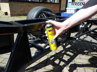
Chassis home safe  first job was to place wax oil in the recess to stop any rust
Did this by removing the body stops and just spraying both ways might help might not

home safe and sound

used 2 tins not a lot
 

Engine hoist

Needed an engine hoist and the promised one fell though so!!! could hire one at £40 a week or buy one at £120 ? decided to buy one and after discussions managed to get Steve to go 50 .50  no brainer really.


New hoist with a box of bits !!
 

Wheels and Chassis

Decided on the wheels early on (well the wife did ) 18 inch so ordered those and had them sent to Andy to make the chassis roll a little bit better


together with tyres sport pilot like other cobra drivers
 
Next great phone call was the rolling chassis is ready  so off I go to pick it up together with the next build kit .


Its Christmas


ENGINE

well what a day today the engine  has finally arrived
pride of place


wiring

Now I have the seat wiring I can complete the loom
Wiring is colour coded for right and left which helps .I also decided to put an extra pair of wires in at the same time just in case .
Drivers side heater cable +2 spares
 Looking at other blogs and the IVA needs clipping at at least 300mm so I copied other blogers and went for 250mm
left hand side has carried the main loom as well
used 6mm clips on the drivers side and 10mm clips on the passenger with stainless self tappers and washers .


Seats and leather gear !

Catching up on the blogs
Seats and all the leather have arrived as needed the dash leather and the heated seat wiring so had to get the lot and store for later on ( happy wife)

Might look better in the car

Wednesday, 3 April 2019

Light wiring

Next task was to start with the wiring started at the drivers side and worked my way round .
Using the GD diagram the wires.  are quite straightforward .
Knowing how much water plays havoc with wiring wanted to make sure in the unlikely event of being caught out in the wet at least the wiring would stay dry .
Placed heat shrink on the headlight  cable so that no water could get in the cables and used the bullet connectors supplied to connect up followed by adhesive tape to seal it all in .
At this point I was not happy with how exposed the indicators were so decided to try and protect them a bit .
After some thought cam up with half a tennis ball  ! I extended the light securing screws with 5mm barrel nuts (tool station ) and then fastened the tennis ball with 2 more 5mm nuts after painting think it look better only time will tell .
Still wet should blend it when dry !

As in the same picture fitted the mesh covers at the same time these were fabricated  by Steve whilst laughing at my tennis ball idea ,he  had to make a wooden template to form the mesh round as the hols were already cut so couldn't use the piece cut out and have to say fitted first time .

Dashboard part 1 of ??

Decided it was high time I tackled the dashboard .
First problem was it didn't fit and when I managed to get it some were near it caught on both the door hinges .
Calls out to Andy ,Dale and the Keith for help found out that the dash need to be square at the ends unlike mine .
needs to be trimmed at the line to fit
Once trimmed it would go in but when setting the dash to be parallel with the transmission tunnel found the top was not leval with the top of the car .
with a bit of sanding and more phone calls it fits
make shift sander
Once I was happy with the fit  then pondered over which layout to go for .This was a lot easier than I thought as I wanted the 5 gauge layout and Annie (the boss) said I was having a clock !! ^ gauge layout it is then

Any layout I want as long as it looks like this !!
The dash has all the marks on it for various layouts so its just a case of making sure the right guide holes are used for the layout I was having .
Measured each gauge and then added 2 mm for the leather to give me the final sizes .
Used a dermal circle cutter for all the gauge holes after first drilling a 3mm pilot hole to allow the point of the cutter to sit in as not to move .
Dusty job so I held the camera !!(what a tidy garage!))

Note the gauge sizes written on the top least I forgot
Itching to have a go

Once the hole were done couldn't resist a trial fit
starting to look the part now ,a lot of work to get this far (note the switch marks )  

Flushed with success the switches and warning lights next .Again measured the diameter and added two mm for the leather .
used a step drill for this ironically the metric one I had was the wrong sizes but the imperial one was just right how strange .
All drilled out and ready to see it in the car .
nice fit and nice smile !
Found the the top gauges were going to foul the top sill as well as 2 of the warning lights which I expected as read on other blogs so marked these as well as the four mounting holes I was going to use .
drilled 2 each side of the big gauges and 2 at the ends .
Drilled them 5 mm in the dash and 6mm in the car to give me a bit of play when the leather goes  on .
sill filed out to clear and the securing holes can be seen

took 2 days but worth the effort